
4.3 Gas Turbines
Gas turbines are an established technology available in sizes ranging from 1 megawatt to over several hundred megawatts. Gas turbines produce high quality heat that can be used for district heating steam requirements, absorption cooling, or industrial processes. Alternatively, this high temperature heat can be recuperated within the gas turbine to improve its power generation efficiency or used to generate hot water or steam. Steam can be generated at high pressure and superheated, then used to drive a steam turbine in a combined-cycle plant. Gas turbine emissions can be controlled to very low levels using either dry combustion techniques, water or steam injection, or exhaust treatment. Maintenance costs per unit of power output are about a third to a half of reciprocating engine generators. Low maintenance and high quality waste heat often make gas turbines a preferred choice for many large commercial or industrial CHP applications greater than 1 MW. Economy of scale also plays a significant role in CHP, Turbines feature the lowest capital cost per MW as well as the lowest maintenance cost of any CHP prime mover for larger CHP systems. A schematic of a gas turbine-based CHP system is shown in Figure 4-5.
Gas turbines can be used in a variety of configurations: (1) simple cycle operation, in which one or more gas turbines produce power only, (2) combined heat and power (CHP) operation which is a simple cycle gas turbine with a heat recovery heat exchanger which recovers the heat from the turbine exhaust and converts it to useful thermal energy usually in the form of steam or hot water, and (3) combined cycle operation in which high pressure, high temperature steam is generated from recovered exhaust heat and used to create additional power using a steam turbine. Some combined cycles extract steam at an intermediate pressure for use in industrial processes and are combined cycle CHP systems.
The most efficient commercial technology for central station power-only generation is the gas turbine-steam turbine combined-cycle plant, with efficiencies approaching 60% (LHV). Simple-cycle gas turbines for power-only generation are available with efficiencies approaching 40% (LHV). Gas turbines have long been used by utilities for peaking capacity. However, with changes in the power industry and advancements in the technology, the gas turbine is now being increasingly used for base-load power.
Gas turbines produce high-quality exhaust heat that can be used in CHP configurations to reach overall system efficiencies (electricity and useful thermal energy) of 70 to 80% (LHV basis) when unfired, even higher if a duct burner is used to elevate the temperature of the gas turbine’s exhaust. By the early 1980s, the efficiency and reliability of smaller gas turbines (1 to 40 MW) had progressed sufficiently to be an attractive choice for industrial and large institutional users for CHP applications.
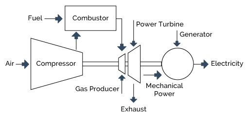
Figure 4-5: Gas Turbine System
4.3.1 Technology Description
Gas turbine systems operate on the thermodynamic cycle known as the Brayton cycle. In a Brayton cycle, atmospheric air is compressed, heated, and then expanded, with the excess of power produced by the expander (also called the turbine) over that consumed by the compressor used for power generation. The power produced by an expansion turbine and consumed by a compressor is proportional to the absolute temperature of the gas passing through the device. Consequently, and particularly in simple cycle applications, it is advantageous to operate the expansion turbine at the highest practical temperature consistent with economic materials and internal blade cooling technology and to operate the compressor with inlet air flow at as low a temperature as possible. As technology advances permit higher turbine inlet temperature, the optimum pressure ratio also increases. Note however that in CHP applications high firing temperature and high pressure ratio do not necessarily improve the system’s financial return.
Higher temperature and pressure ratios result in higher efficiency and specific power. Thus, the general trend in gas turbine advancement has been towards a combination of higher temperatures and pressures. While such advancements increase the manufacturing cost of the machine, the higher value, in terms of greater power output and higher efficiency, can provide net economic benefits. The industrial gas turbine is a balance between performance and cost that results in the most economic machine for both the user and manufacturer. Gas turbine exhaust is quite hot, up to 800 to 900° F for smaller industrial turbines and up to 1,100° F for some new, large central station utility machines and aeroderivative turbines. Such high exhaust temperatures permit direct use of the exhaust. With the addition of a heat recovery steam generator, the exhaust heat can produce steam or hot water. A portion or all of the steam generated by the HRSG may be used to generate additional electricity through a steam turbine in a combined cycle configuration.
There are two basic types of gas turbines:
Aeroderivative gas turbines for stationary power are adapted from their jet and turboshaft aircraft engine counterparts. While these turbines are lightweight and thermally efficient, they are usually more expensive than products designed and built exclusively for stationary applications. The largest aeroderivative generation turbines available are 40 to 50 MW in capacity. Many aeroderivative gas turbines for stationary use operate with compression ratios in the range of 30:1, requiring a high-pressure external fuel gas compressor. With advanced system developments, larger aeroderivative turbines (>40 MW) are approaching 45% simple-cycle efficiencies (LHV).
Industrial or frame gas turbines are exclusively for stationary power generation and are available in the 1 to 350 MW capacity range. They are generally less expensive, more rugged, can operate longer between overhauls, and are more suited for continuous base-load operation with longer inspection and maintenance intervals than aeroderivative turbines. However, they are less efficient and much heavier. Industrial gas turbines generally have more modest compression ratios (up to 16:1) and often do not require an external fuel gas compressor. Larger industrial gas turbines (>100 MW) are approaching simple-cycle efficiencies of approximately 40% (LHV) and combined-cycle efficiencies of 60% (LHV). It’s important to note that in CHP applications, simple cycle efficiency does not have a significant role in determining CHP efficiency. It’s quite possible for a turbine with low simple cycle efficiency to have a better CHP efficiency than a turbine with higher simple cycle efficiency. This is especially true in fired CHP applications, and those make up the majority of industrial gas turbine CHP installations.
Industry uses gas turbines between 500 kW to 40 MW for on-site power generation and as mechanical drivers. Small gas turbines also drive compressors on long distance natural gas pipelines. In the petroleum industry turbines drive gas compressors to maintain well pressures and enable refineries and petrochemical plants to operate at elevated pressures. In the steel industry turbines drive air compressors used for blast furnaces. In process industries such as chemicals, refining and paper, and in large commercial and institutional applications turbines are used in combined heat and power mode generating both electricity and steam for use on-site.
4.3.2 Performance
Table 4-3 summarizes performance characteristics for typical commercially available gas turbine CHP systems over the 1 to 40 MW size range. Heat rates shown are from manufacturers’ specifications and industry publications. Available thermal energy (steam output) was calculated from published turbine data on turbine exhaust temperatures and flows. CHP steam estimates are based on an unfired HRSG with an outlet exhaust temperature of 280° F producing dry, saturated steam at 150 psig. Total efficiency is defined as the sum of the net electricity generated plus steam produced for plant thermal needs divided by total fuel input to the system. Higher steam pressures can be obtained but at slightly lower total efficiencies. As mentioned earlier, additional steam can be generated and total efficiency further increased with duct firing in the HRSG (see heat recovery section). To estimate fuel savings effective electrical efficiency is a more useful value than overall efficiency. Effective electric efficiency is calculated assuming the useful-thermal output from the CHP system would otherwise be generated by an 80% efficient boiler. The theoretical boiler fuel is subtracted from the total fuel input and the remaining fuel input used to calculate the effective electric efficiency which can then be compared to traditional electric generation.
Gas turbines need minimum gas pressure of about 100 psig for the smallest turbines with substantially higher pressures for larger turbines and aeroderivative machines. Depending on the supply pressure of the gas being delivered to the site the cost and power consumption of the fuel gas compressor can be a significant consideration. Table 4-4 shows the power required to compress natural gas from supply pressures typical of commercial and industrial service to the pressures required by typical industrial gas turbines. Required supply pressures generally increase with gas turbine size.
Table 4-3: Gas Turbine CHP – Typical Performance Parameters
| Cost & Performance Characteristics | System | ||||
|---|---|---|---|---|---|
| 1 | 2 | 3 | 4 | 5 | |
| Net Electricity Capacity (kW) | 3,304 | 7,038 | 9,950 | 20,336 | 44,488 |
| Installed Cost (2013 $/kW) | $3,281 | $2,080 | $1,976 | $1,518 | $1,248 |
| Electric Heat Rate (Btu/kWh), HHV | 14,247 | 11,807 | 12,482 | 10,265 | 9,488 |
| Electrical Efficiency (%), HHV | 23.95% | 28.90% | 27.34% | 33.24% | 35.96% |
| Fuel Input (MMBtu/hr), HHV | 47.1 | 83.1 | 124.2 | 208.7 | 422.1 |
| Required Fuel Gas Pressure (psig) | 166.8 | 299.4 | 362.3 | 405.2 | 538 |
| CHP Characteristics | |||||
| Exhaust Flow (1,000 lb/hr) | 149.2 | 211.6 | 334 | 536 | 1047 |
| GT Exhaust Temperature (Fahrenheit) | 838 | 916 | 913 | 974 | 861 |
| HRSG Exhaust Temperature (Fahrenheit) | 336 | 303 | 322 | 326 | 300 |
| Steam Output (MMBtu/hr) | 19.66 | 34.44 | 52.36 | 77.82 | 138.72 |
| Steam Output (kW equivalent) | 5,760 | 10,092 | 15,340 | 22,801 | 40,645 |
| Total CHP Efficiency (%), HHV | 65.7% | 70.4% | 69.5% | 70.5% | 68.8% |
| Power/Heat Ratio | 0.57 | 0.71 | 0.65 | 0.89 | 1.09 |
| Net Heat Rate (Btu/kWh) | 6,810 | 5,689 | 5,905 | 5,481 | 5,590 |
| Effective Electrical Efficiency (%) | 50% | 60% | 58% | 62% | 61% |
| Thermal Output as Fraction of Fuel Input | 0.42 | 0.41 | 0.42 | 0.37 | 0.33 |
| Electric Output as Fraction of Fuel Input | 0.24 | 0.29 | 0.27 | 0.33 | 0.36 |
Table 4-4: Power Requirements for Natural Gas Compression (1)
| Turbine Conditions | System | ||||
|---|---|---|---|---|---|
| 1 | 2 | 3 | 4 | 5 | |
| Turbine Electric Capacity (kW) | 3,304 | 7,038 | 9,950 | 20,336 | 44,488 |
| Turbine Pressure Ratio | 10.1 | 17.6 | 17.7 | 24 | 31.9 |
| Pressure Required, psig | 167 | 299 | 362 | 405 | 538 |
| Required Compression Power (kW) | |||||
| 55 psig gas supply pressure | 51 | 162 | 289 | 538 | 1,370 |
| 150 psig gas supply pressure | 21 | 63 | 113 | 211 | 510 |
| 250 psig gas supply pressure | NA | 39 | 70 | 131 | 310 |
4.3.3 Emissions
The primary pollutants from gas turbines are oxides of nitrogen (NOx), carbon monoxide (CO), and volatile organic compounds (VOCs). Other pollutants such as oxides of sulfur (SOx) and particulate matter (PM) are primarily dependent on the fuel used. The sulfur content of the fuel determines emissions of sulfur compounds, primarily SO2. Gas turbines operating on desulfized natural gas or distillate oil emit relatively insignificant levels of SOx. In general, SOx emissions are greater when heavy oils are fired in the turbine. SOx control is thus a fuel purchasing issue rather than a gas turbine technology issue. Particulate matter is a marginally significant pollutant for gas turbines using liquid fuels. Ash and metallic additives in the fuel may contribute to PM in the exhaust.
It is important to note that the gas turbine operating load has a significant effect on the emissions levels of the primary pollutants of NOx, CO, and VOCs. Gas turbines typically operate at high loads. Consequently, gas turbines are designed to achieve maximum efficiency and optimum combustion conditions at high loads. Controlling all pollutants simultaneously at all load conditions is difficult. At higher loads, higher NOx emissions occur due to peak flame temperatures. At lower loads, lower thermal efficiencies and more incomplete combustion occurs resulting in higher emissions of CO and VOCs. See the previous discussion of NOx formation in (section 4.2.3).
The focus of turbine NOx control and combustion improvements of the past decade was to lower flame hot spot temperatures using lean fuel/air mixtures and pre-mixed combustion. Lean combustion decreases the fuel/air ratio in the zones where NOx production occurs so that the peak flame temperature is less than the stoichiometric adiabatic flame temperature, therefore suppressing thermal NOx formation.
Lean premixed combustion (DLN/DLE) pre-mixes the gaseous fuel and compressed air so that there are no local zones of high temperatures, or “hot spots,” where high levels of NOx would form. Lean premixed combustion requires specially designed mixing chambers and mixture inlet zones to avoid flashback of the flame. Optimized application of DLN combustion requires an integrated approach to combustor and turbine design. The DLN combustor becomes an intrinsic part of the turbine design, and specific combustor designs must be developed for each turbine application. While NOx levels as low as 9 ppm have been achieved with lean premixed combustion few DLN equipped turbines have reached the level of practical operation at this emissions level necessary for commercialization – the capability of maintaining 9 ppm across a wide operating range from full power to minimum load. One problem is that pilot flames, which are small diffusion flames and a source of NOx, are usually used for continuous internal ignition and stability in DLN combustors and make it difficult to maintain full net NOx reduction
over the complete turndown range.
Noise can also be an issue in lean premixed combustors as acoustic waves form due to combustion instabilities when the premixed fuel and air ignite. This noise also manifests itself as pressure waves, which can damage combustor walls and accelerate the need for combustor replacement, thereby adding to maintenance costs and lowering unit availability.
All leading gas turbine manufacturers feature DLN combustors in at least parts of their product lines. Turbine manufacturers generally guarantee NOx emissions of 15 to 42 ppm using this technology. NOx emissions when firing distillate oil are typically guaranteed at 42 ppm with DLN and/or combined with water injection. A few models (primarily those larger than 40 MW) have combustors capable of 9 ppm (natural gas fired) over the range of expected operation.
The development of market-ready DLN equipped turbine models is an expensive undertaking because of the operational difficulties in maintaining reliable gas turbine operation over a broad power range. Therefore, the timing of applying DLN to multiple turbine product lines is a function of market priorities and resource constraints. Gas turbine manufacturers initially develop DLN combustors for the gas turbine models for which they expect the greatest market opportunity. As time goes on and experience is gained, the technology is extended to additional gas turbine models.
The primary post-combustion NOx control method in use today is selective catalytic reduction (SCR). Ammonia is injected into the flue gas and reacts with NOx in the presence of a catalyst to produce N2 and H2O. The SCR system is located in the exhaust path, typically within the HRSG where the temperature of the exhaust gas matches the operating temperature of the catalyst. The operating temperature of conventional SCR systems ranges from 400 to 800° F. The cost of conventional SCR has dropped significantly over time — catalyst innovations have been a principal driver, resulting in a 20% reduction in catalyst volume and cost with no change in performance.
Low temperature SCR, operating in the 300 to 400 ° F temperature range, was commercialized in 1995 and is currently in operation on approximately twenty gas turbines. Low temperature SCR is ideal for retrofit applications where it can be located downstream of the HRSG, avoiding the potentially expensive retrofit of the HRSG to locate the catalyst within a hotter zone of the HRSG.
High temperature SCR installations, operating in the 800 to 1,100° F temperature range, have increased significantly in recent years. The high operating temperature permits the placement of the catalyst directly downstream of the turbine exhaust flange. High temperature SCR is also used on peaking capacity and base-loaded simple-cycle gas turbines where there is no HRSG.
SCR reduces between 80 to 90% of the NOx in the gas turbine exhaust, depending on the degree to which the chemical conditions in the exhaust are uniform. When used in series with water/steam injection or DLN combustion, SCR can result in low single digit NOx levels (2 to 5 ppm).
SCR systems are expensive and significantly impact the economic feasibility of smaller gas turbine projects. For a 5 MW project electric generation costs increase approximately half a cent per kWh. In addition, SCR requires on-site storage of ammonia, a hazardous chemical. Finally, ammonia can “slip” through the process unreacted, contributing to environmental health concerns.
4.3.4 CHP Applications
The economics of gas turbines in process applications often depend on effective use of the thermal energy contained in the exhaust gas, which generally represents 60 to 70% of the inlet fuel energy. Figure 4-6 shows a typical gas turbine/HRSG configuration. An unfired HRSG is the simplest steam CHP configuration and can generate steam at conditions ranging from 150 psig to approximately 1,200 psig.
Gas turbine exhaust can also be used for heat and drying process either directly or by means of a heat exchanger.
4.3.5 Thermal Energy Generation
Gas turbines produce a high quality (high temperature) thermal output suitable for most combined heat and power applications. High-pressure steam can be generated or the exhaust can be used directly for process drying and heating.
Overall or total efficiency of a CHP system is a function of the amount of energy recovered from the turbine exhaust. The two most important factors influencing the amount of energy available for steam generation are gas turbine exhaust temperature and HRSG stack temperature.
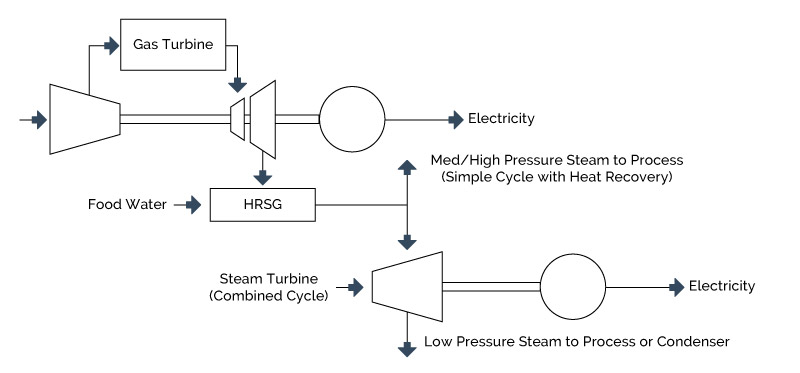
Figure 4-6: Heat Recovery from a Gas Turbine System
Turbine firing temperature and turbine pressure ratio combined determine gas turbine exhaust temperature. Typically aeroderivative gas turbines have higher firing temperatures than do industrial gas turbines, but when the higher pressure ratio of aeroderative gas turbines is recognized, the turbine discharge temperatures of the two turbine types remain somewhat close, typically in the range of 850 to 950° F. For the same HRSG exit temperature, higher turbine exhaust temperature (higher HRSG gas inlet temperature) results in greater available thermal energy, increased HRSG output, and higher CHP efficiency.
Similarly, the lower the HRSG stack temperature, the greater the amount of energy recovered and the higher the total-system efficiency. HRSG stack temperature is a function of steam conditions and fuel type. Saturated steam temperatures increase with increasing steam pressure. Because of pinch point considerations within the HRSG, higher steam pressures result in higher HRSG exhaust stack temperatures, less utilization of available thermal energy, and a reduction in total CHP system efficiency. In general, minimum stack temperatures of about 300° F are recommended for sulfur bearing fuels. Generally, unfired HRSGs can be designed to economically recover approximately 95% the available energy in the turbine exhaust (the energy released in going from turbine exhaust temperature to HRSG exhaust temperature).
Since very little of the available oxygen in the turbine air flow is used in the combustion process, the oxygen content in the gas turbine exhaust permits supplementary fuel firing ahead of the HRSG to increase steam production relative to an unfired unit. Supplementary firing can raise the exhaust gas temperature entering the HRSG up to 2,600° F and increase the amount of steam produced by the unit by a factor of four. Moreover, since the turbine exhaust gas is essentially preheated combustion air, the fuel consumed in supplementary firing is less than that required for a stand-alone boiler providing the same increment in steam generation. The HHV efficiency of incremental steam production from supplementary firing above that of an unfired HRSG is often 85% or more when firing natural gas.
Supplementary firing also increases system flexibility. Unfired HRSGs are typically convective heat exchangers that respond solely to exhaust conditions of the gas turbine and do not easily allow for steam flow control. Supplementary firing capability provides the ability to control steam production, within the capability of the burner system, independent of the normal gas turbine operating mode. Low NOx duct burners with guaranteed emissions levels as low as 0.08 lb NOx/MMBtu can be specified to minimize the NOx contribution of supplemental firing.
4.3.6 Current Market Applications
The oil and gas industry commonly use gas turbines to drive pumps and compressors, process industries use them to drive compressors and other large mechanical equipment, and many industrial and institutional facilities use turbines to generate electricity for use on-site. When used to generate power on-site, gas turbines are often used in combined heat and power mode where energy in the turbine exhaust provides thermal energy to the facility.
There were an estimated 40,000 MW of gas turbine based CHP capacity operating in the United States in 2000
located at over 575 industrial and institutional facilities. Much of this capacity is concentrated in large combined cycle CHP systems that maximize power production for sale to the grid. However, a significant number of simple cycle gas turbine based CHP systems are in operation at a variety of applications as shown in Figure 4-7. Simple cycle CHP applications are most prevalent in smaller installations, typically less than 40 MW.
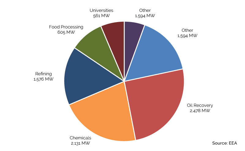
Figure 4-7: Existing Simple Cycle Gas Turbine CHP
Gas turbines are ideally suited for CHP applications because their high-temperature exhaust can be used to generate process steam at conditions as high as 1,200 pounds per square inch gauge (psig) and 900 degree Fahrenheit (°F) or used directly in industrial processes for heating or drying. A typical industrial CHP application for gas turbines is a chemicals plant with a 25 MW simple cycle gas turbine supplying base-load power to the plant with an unfired heat recovery steam generator (HRSG) utilizing the exhaust. Approximately 29 MW thermal (MWth) of steam is produced for process use within the plant.
A typical commercial/institutional CHP application for gas turbines is a college or university campus with a 5 MW simple-cycle gas turbine. Approximately 8 MWth of 150 to 400 psig steam (or hot water) is produced in an unfired heat recovery steam generator and sent into a central thermal loop for campus space heating during winter months or to single-effect absorption chillers to provide cooling during the summer. Because duct firing can improve CHP efficiency dramatically, as well as the steam flexibility noted above, most of the installations in this size range (roughly 75%) employ duct firing.
While the recovery of thermal energy provides compelling economics for gas turbine CHP, smaller gas turbines supply prime power in certain applications. Large industrial facilities install simple-cycle gas turbines without heat recovery to provide peaking power in capacity constrained areas, and utilities often place gas turbines in the 5 to 40 MW size range at substations to provide incremental capacity and grid support. A number of turbine manufacturers and packagers offer mobile turbine generator units in this size range that can be used in one location during a period of peak demand and then trucked to another location for the following season. Another recent innovation is the modular power plant (MPP) which uses the modules from the mobile power plant, including its “plug-and-play” electrical connections. The MPP modules are not mounted on trailers as they are intended to stay in one location. The benefit of the MPP design is flexibility in MW size and steam output, as well as quick installation and commissioning schedules.
4.3.7 CHP Potential
The benefits of gas turbines used in CHP stem from the high temperature and flow rate of gas turbine exhaust. The economics of gas turbines in process applications depend on effective use of the thermal energy contained in the exhaust gas, which generally represents 60 to 70% of the inlet fuel energy. The most common use of this energy is for steam generation in unfired or supplementary fired heat recovery steam generators. However, the gas turbine exhaust gases can also be used as a source of direct process energy, for unfired or fired process fluid heaters, or as preheated combustion air for power boilers. Overall or total efficiency of a CHP system is a function of the amount of energy recovered from the turbine exhaust. The two most important factors influencing the amount of energy available for steam generation are gas turbine exhaust temperature and HRSG stack temperature.
- Fuel gas supply pressure requirements calculated assuming delivery of natural gas at an absolute pressure roughly 35% greater than the compressor discharge in order to meet the requirements of the gas turbine flow control system and combustor mixing nozzles. Mass flow of fuel based on the fuel flow of reference gas turbines in the size range considered, and assuming an electric motor of 95% efficiency driving the booster compressor. Gas supply pressures of 50 psig, 150 psig and 250 psig form the basis of the calculations.
- Cost Analysis of NOx Control Alternatives for Stationary Gas Turbines , ONSITE SYCOM Energy Corporation